The Y6-30 boiler induced draft fan is designed for extracting boiler flue gas and maintaining stable negative pressure in industrial boiler systems. It can be supplied with C-type or D-type drive, left-hand or right-hand rotation, and multiple outlet-angle arrangements.
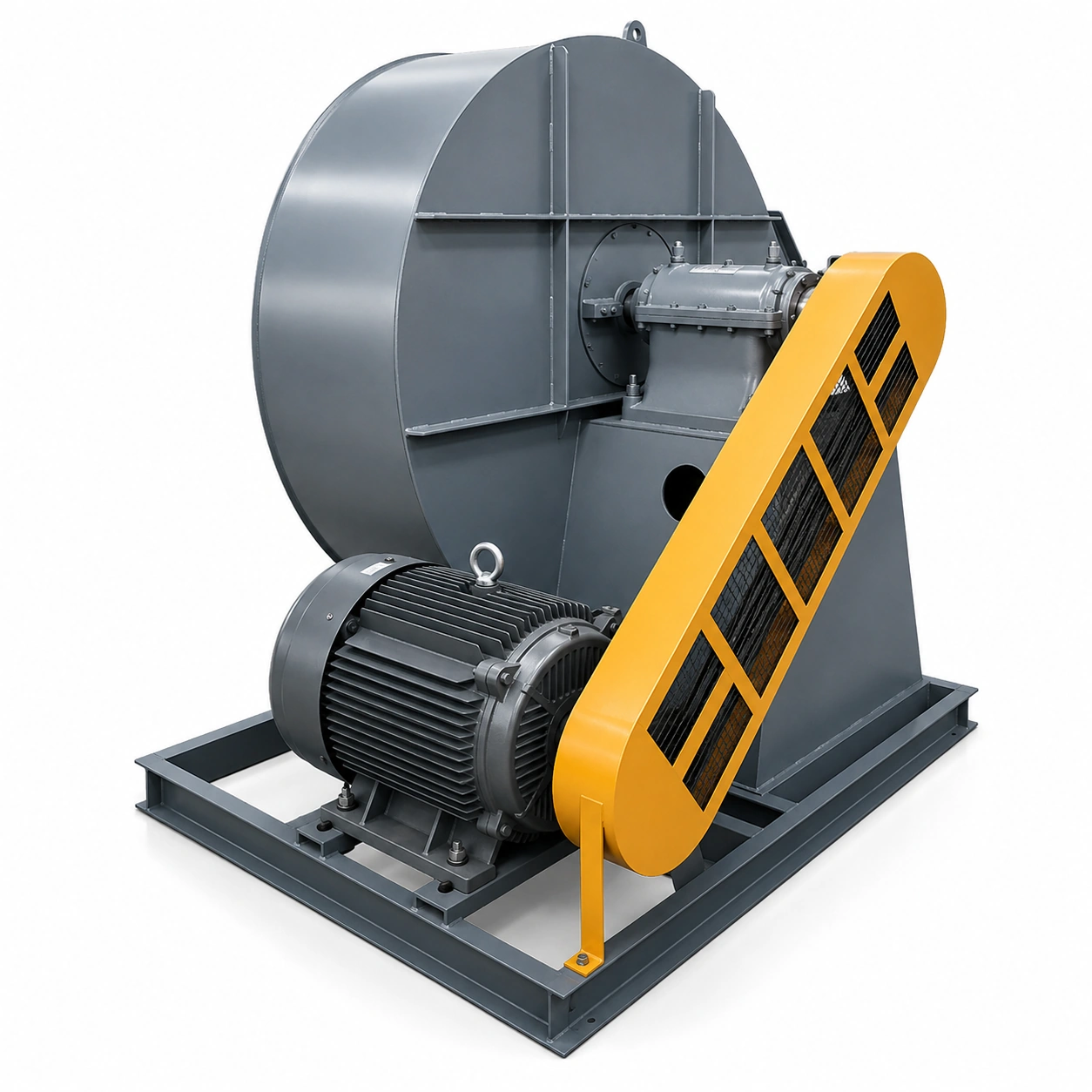
The fan is mainly composed of the impeller, casing, air inlet, air-regulating damper and transmission assembly. Available fan sizes, motor power, speed, airflow and total pressure should be selected according to the actual boiler capacity and system resistance.
Qiyue Fan can configure the motor voltage, drive arrangement, rotation direction, outlet angle, surface treatment and material according to the operating temperature, gas composition, dust concentration and installation requirements. Stainless-steel or corrosion-resistant configurations are available subject to project confirmation.
Designed for boiler induced-draft systems that require stable flue-gas extraction, controlled negative pressure and flexible installation arrangements.
C-Type / D-Type Drive
Left / Right Rotation
Multiple Outlet Angles
Fan Size
3.5–8.6
Airflow
655–17,262 m³/h
Pressure
727–3,226 Pa
Motor Power
0.75–22 kW
Product Overview
A Configurable Boiler Induced Draft Fan for Stable System Draft
The Y6-30 boiler induced draft fan is used to extract combustion flue gas and maintain the negative pressure required by the boiler system. It can be selected for small and medium boiler installations according to the required airflow, total pressure, boiler capacity and site layout.
The series is available with C-type or D-type drive. Rotation direction, outlet angle, motor specification and material can be configured according to the project. Final selection should be based on the actual system resistance, gas temperature, gas composition and expected operating point.
Typical Selection Inputs
Required airflow at operating condition
Required total pressure and system resistance
Flue-gas temperature and dust concentration
Motor voltage, frequency and protection level
Rotation direction and outlet angle
Drive, Rotation and Outlet Arrangement
C-Type Drive
The impeller is driven through a belt transmission. This arrangement supports speed matching and is suitable where flexible motor positioning is required.
D-Type Drive
The impeller is directly connected to the motor shaft. The applicable model and motor configuration should be confirmed for the project.
Outlet Direction
Standard 0° outlet is available. Required configurations may include 45°, 90°, 135°, 180° and 225° for left-hand or right-hand rotation.
Main Components and Working Structure
Impeller
The impeller consists of multiple blades, a curved front plate and a flat rear plate. It converts mechanical energy into airflow and pressure.
Casing
The volute casing collects the gas discharged from the impeller and guides it toward the outlet while reducing unnecessary flow loss.
Air Inlet
The inlet directs flue gas smoothly into the impeller eye and helps maintain stable inlet flow conditions.
Air-Regulating Damper
The damper supports operating adjustment during commissioning and can help match the actual system resistance.
Transmission Assembly
The drive assembly includes the shaft, bearing components, coupling or belt components according to the selected arrangement.
Motor and Base
The motor and structural base are selected to match fan size, speed, power and installation requirements.
Application Range
Typical Boiler and Flue-Gas Applications
Industrial steam boilers
Hot-water boiler systems
Biomass boiler exhaust
Coal-fired boiler draft
Flue-gas extraction
Dust-removal system exhaust
Furnace negative-pressure control
Process exhaust systems
Material and Project Configuration
Standard Configuration
The standard material and surface treatment should be selected according to flue-gas temperature, dust loading and corrosion conditions. Motor, bearing, guard and base configuration are matched to the selected fan size.
Optional Customization
Available project options may include stainless-steel components, corrosion-resistant coating, high-temperature configuration, customized motor voltage, vibration isolation and non-standard outlet arrangement, subject to factory confirmation.
Y6-30 Performance Parameters
The following performance data is transcribed from the supplied factory table. Values marked with an asterisk should be checked against the original performance sheet before final publication.
Size
Drive
Speed
r/min
Pressure
Pa
Airflow
m³/h
Efficiency
%
Motor Model
Power
kW
Boiler
t/h
3.5
C
2350
853
655
66.0
Y801-2B3
0.75
0.2
3.5
C
2350
843
745
68.0
Y801-2B3
0.75
0.2
3.5
C
2350
834
834
70.0
Y801-2B3
0.75
0.2
3.5
C
2350
824
923
72.0
Y801-2B3
0.75
0.2
3.5
C
2350
800
1000
72.0
Y801-2B3
0.75
0.2
3.5
C
2350
765
1103
66.0
Y801-2B3
0.75
0.2
3.5
C
2350
727
1192
63.0
Y801-2B3
0.75
0.2
4.3
C
2260*
1206
1169
66.0
Y90S-2B3
1.5
0.2
4.3
C
2260*
1187
1328
68.0
Y90S-2B3
1.5
0.2
4.3
C
2260*
1176
1487
70.5
Y90S-2B3
1.5
0.2
4.3
C
2260*
1170
1700
71.0
Y90S-2B3
1.5
0.2
4.3
C
2260*
1108
1806
70.0
Y90S-2B3
1.5
0.2
4.3
C
2260*
1078
1966
67.0
Y90S-2B3
1.5
0.2
4.3
C
2260*
1020
2125
64.0
Y90S-2B3
1.5
0.2
4.8
C
2250
1490
1919
66.0
Y90L-2B3
2.2
0.5
4.8
C
2250
1470
1840
68.0
Y90L-2B3
2.2
0.5
4.8
C
2250
1450
1060*
70.5
Y90L-2B3
2.2
0.5
4.8
C
2250
1420
2300
72.0
Y90L-2B3
2.2
0.5
4.8
C
2250
1392
2503
71.0
Y90L-2B3
2.2
0.5
4.8
C
2250
1333
2723
68.0
Y90L-2B3
2.2
0.5
4.8
C
2250
1265
2944
65.0
Y90L-2B3
2.2
0.5
5.4
C
2300
2157
2202
66.0
Y100L-2B3
3
0.5
5.4
C
2300
2128
2503
68.0
Y100L-2B3
3
0.5
5.4
C
2300
2908*
2804
70.5
Y100L-2B3
3
0.5
5.4
C
2300
2060
3100
73.0
Y100L-2B3
3
0.5
5.4
C
2300
1981
3405
70.0
Y100L-2B3
3
0.5
5.4
C
2300
1922
3705
68.0
Y100L-2B3
3
0.5
5.4
C
2300
1833
3963
66.0
Y100L-2B3
3
0.5
6.5
C
2150
2383
2926
77.0
Y112M-2B3
4
1
6.5
C
2150
2433
3325
79.0
Y112M-2B3
4
1
6.5
C
2150
2328
3725
80.0
Y112M-2B3
4
1
6.5
C
2150
2288
4000
81.5
Y112M-2B3
4
1
6.5
C
2150
2206
4263
81.0
Y132S1-2B3
5.5
1
6.5
C
2150
2137
4604
80.0
Y132S1-2B3
5.5
1
6.5
C
2150
2020
4945
77.5
Y132S1-2B3
5.5
1
7.5
C
1900
2598
5216
77.5
Y132M-4B3
7.5
2
7.5
C
1900
2559
5926
79.0
Y132M-4B3
7.5
2
7.5
C
1900
2530
6622
80.0
Y132M-4B3
7.5
2
7.5
C
1900
2500
6600*
81.5
Y132M-4B3
7.5
2
7.5
C
1900
2392
7349
81.2
Y160M-4B3
11
2
7.5
C
1900
2324
8060
80.0
Y160M-4B3
11
2
7.5
C
1900
2196
8771
77.5
Y160M-4B3
11
2
7.5
C
1800
2736
5000
78.0
Y132M-4B3
7.5
2
7.5
C
1800
2726
5500
81.0
Y132M-4B3
7.5
2
7.5
C
1800
2716
5900
82.0
Y132M-4B3
7.5
2
7.5
C
1800
2598
6200
82.0
Y132M-4B3
7.5
2
7.5
C
1800
2530
6500
80.0
Y160M-4B3
11
2
7.5
C
1800
2500
7000
78.0
Y160M-4B3
11
2
7.5
C
1800
2432
7800
76.0
Y160M-4B3
11
2
8.6
C
1850
3226
9494
78.0
Y180M-4B3
18.5
4
8.6
C
1850
3187
10789
80.0
Y180M-4B3
18.5
4
8.6
C
1850
3138
12083
81.3
Y180M-4B3
18.5
4
8.6
C
1850
3098
12778
82.0
Y180M-4B3
18.5
4
8.6
C
1850
3040
14000
81.5
Y180L-4B3
22
4
8.6
C
1850
2883
15967
80.0
Y180L-4B3
22
4
8.6
C
1850
2736
17262
77.5
Y180L-4B3
22
4
Data verification: The source image contains several values that appear inconsistent, including 4.3 speed, one 4.8 airflow point, one 5.4 pressure point and one 7.5 airflow point. They are retained with an asterisk and should be verified before publishing.
How to Select the Correct Y6-30 Fan
1. Confirm the Operating Point
Provide design airflow and total pressure after considering duct resistance, equipment resistance and required reserve.
2. Confirm the Medium
State gas temperature, dust concentration, moisture and corrosive components so the material and bearing arrangement can be checked.
3. Confirm Installation
Specify C-type or D-type drive, motor requirements, rotation direction, outlet angle, base arrangement and available installation space.
Quality Control and Delivery
Impeller dimensional inspection
Dynamic balance verification
Rotation and vibration check
Motor and guard inspection
Surface and coating inspection
Nameplate and direction marking
Export packing confirmation
Document and accessory check
Frequently Asked Questions
What information is required to select a Y6-30 boiler induced draft fan?
Please provide airflow, total pressure, gas temperature, gas composition, dust concentration, motor voltage, installation space, rotation direction and outlet angle.
Can the Y6-30 fan be supplied in left-hand and right-hand rotation?
Yes. Rotation is determined when viewed from the motor side and should be confirmed together with the required outlet angle.
Which outlet angles are available?
The standard outlet is 0°. Other arrangements such as 45°, 90°, 135°, 180° and 225° can be considered according to installation requirements.
Can the motor voltage and frequency be customized?
Yes. Motor voltage, frequency, protection level and insulation class can be matched to the destination market and operating environment.
Is stainless-steel construction available?
Stainless-steel components or other corrosion-resistant configurations can be evaluated according to the medium and project requirements.
Selection Support
Send Us Your Boiler Operating Data
Qiyue Fan can match the fan size, drive arrangement, motor, material, rotation direction and outlet angle to your project.