

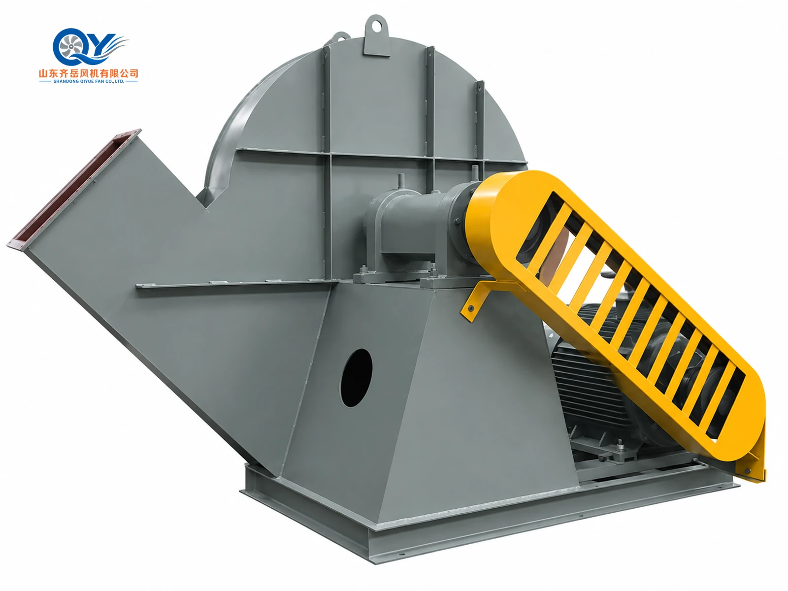
The 10-24 high-pressure centrifugal fan is designed for forging-furnace air supply, sulfuric-acid furnace-bottom ventilation, industrial forced draft, process air and selected dry-material conveying duties where the system requires high pressure.
The documented series covers No.6.8 to No.8.5, with airflow from 7,210 to 20,178 m³/h and total pressure from 11,920 to 19,964 Pa at a reference fan speed of 2960 r/min.
Final fan size, motor, rotation and discharge angle should be confirmed from the actual duty point and installation requirement.
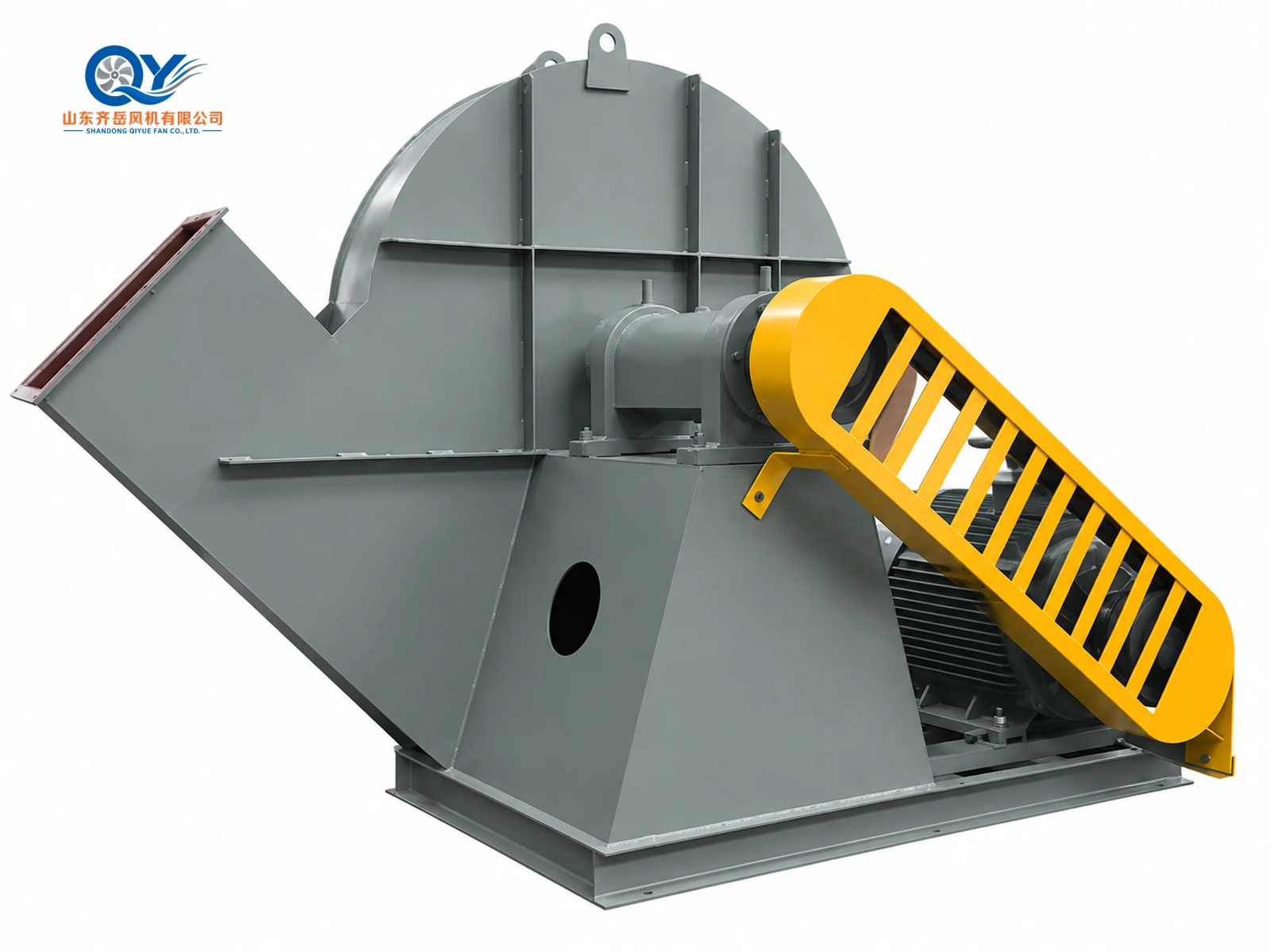
High Pressure for Furnace Forced Draft and Industrial Air Systems
The 10-24 series is a pressure-oriented centrifugal fan for applications where ordinary ventilation fans cannot provide sufficient pressure. The original catalogue lists forging-furnace air supply, sulfuric-acid furnace-bottom ventilation, general high-pressure forced draft and material conveying.
The conveyed medium should generally be non-corrosive, non-self-igniting and non-sticky. Catalogue guidance states that medium temperature should generally not exceed 80°C and dust or hard-particle content should not exceed 150 mg/m³.
For combustion-air projects, review the Industrial Forced Draft Fan System. Final selection should then be confirmed from airflow, total pressure, medium, temperature, motor, rotation, discharge angle and installation space.
10-24 Series Technical Parameters
10-24 Performance by Fan Size
The table below reproduces the documented 30 operating points for No.6.8, 7.1, 7.4, 8 and 8.5, including total pressure, airflow, required power and matching motor data.
Reference condition: inlet-air temperature 20°C, density 1.2 kg/m³, atmospheric pressure 101325 Pa and fan speed 2960 r/min.
| Fan Size | Point | Total Pressure Pa |
Airflow m³/h |
Required Power kW |
Motor Model | Motor Power kW |
|---|---|---|---|---|---|---|
| 6.8 | 1 | 11,920 | 7,210 | 36.96 | Y225M-2 | 45 |
| 6.8 | 2 | 12,220 | 8,610 | 44.2 | Y225M-2 | 45 |
| 6.8 | 3 | 12,440 | 10,020 | 52.43 | Y250M-2 | 55 |
| 6.8 | 4 | 12,570 | 11,420 | 61.81 | Y280S-2 | 75 |
| 6.8 | 5 | 12,570 | 12,830 | 71.82 | Y280S-2 | 75 |
| 6.8 | 6 | 12,290 | 14,230 | 80.86 | Y280M-2 | 90 |
| 7.1 | 1 | 13,000 | 8,200 | 45.84 | Y250M-2 | 55 |
| 7.1 | 2 | 13,320 | 9,800 | 54.83 | Y250M-2 | 55 |
| 7.1 | 3 | 13,560 | 11,400 | 65.02 | Y280S-2 | 75 |
| 7.1 | 4 | 13,700 | 13,000 | 76.69 | Y280M-2 | 90 |
| 7.1 | 5 | 13,700 | 14,600 | 89.07 | Y280M-2 | 90 |
| 7.1 | 6 | 13,400 | 16,200 | 100.37 | Y315S-2 | 110 |
| 7.4 | 1 | 14,120 | 9,290 | 56.41 | Y280S-2 | 75 |
| 7.4 | 2 | 14,470 | 11,100 | 67.47 | Y280S-2 | 75 |
| 7.4 | 3 | 14,730 | 12,910 | 79.98 | Y280M-2 | 90 |
| 7.4 | 4 | 14,880 | 14,720 | 94.32 | Y315S-2 | 110 |
| 7.4 | 5 | 14,880 | 16,530 | 109.53 | Y315S-2 | 110 |
| 7.4 | 6 | 14,556 | 18,340 | 123.43 | Y315M-2 | 132 |
| 8 | 1 | 16,919 | 7,850 | 52.1 | Y280S-2 | 75 |
| 8 | 2 | 17,512 | 9,614 | 63.3 | Y280S-2 | 75 |
| 8 | 3 | 17,675 | 11,439 | 74.8 | Y280S-2 | 75 |
| 8 | 4 | 17,675 | 13,233 | 87.2 | Y280M-2 | 90 |
| 8 | 5 | 17,481 | 15,028 | 100.3 | Y315S-2 | 110 |
| 8 | 6 | 17,257 | 16,822 | 114.1 | Y315S-2 | 110 |
| 8.5 | 1 | 19,106 | 9,416 | 70.6 | Y280M-2 | 90 |
| 8.5 | 2 | 19,769 | 11,568 | 85.1 | Y280M-2 | 90 |
| 8.5 | 3 | 19,964 | 13,721 | 101.4 | Y315S-2 | 110 |
| 8.5 | 4 | 19,964 | 15,873 | 116.1 | Y315M-2 | 132 |
| 8.5 | 5 | 19,729 | 18,025 | 135.9 | Y315L1-2 | 160 |
| 8.5 | 6 | 19,481 | 20,178 | 154.4 | Y315L1-2 | 160 |
Heavy-Duty Coupling-Driven Centrifugal Construction
Impeller
High-pressure centrifugal impeller for the documented 10-24 performance range.
Volute Casing
Welded casing collecting flow from the impeller and directing it to the discharge outlet.
Inlet
Streamlined inlet geometry feeding air into the impeller eye.
Shaft & Bearing Group
Separate shaft and bearing support shown in the documented installation drawings.
Coupling
Coupling transmits motor power to the fan shaft and requires correct alignment during installation.
Motor & Common Base
Motor and fan group are arranged on the supporting base. Final motor configuration affects overall dimensions.
10-24 Outline and Installation Drawings
Use the drawings together with the selected fan size and motor configuration before foundation, duct or support fabrication.


For guidance on checking installation interfaces, see the Industrial Fan GA Drawing Guide.
10-24 Installation Dimension Tables
Dimensions are in millimetres. The original dimensional schedule distinguishes between standard motor configurations and units using Y315S-2, Y315M-2 or Y315L1-2 motors.
| Size | A1 | A2 | A3 | A4 | A5 | A6 | A7 | A8 | D1 | D2 | D3 | Inlet Holes | K | F | E | C |
|---|---|---|---|---|---|---|---|---|---|---|---|---|---|---|---|---|
| 6.8 | 100 | 340 | 382 | 406 | 100 | 192 | 237 | 261 | 383 | 432 | 485 | 8-Φ12 | 503 | 497 | 185.5 | 580 |
| 7.1 | 100 | 355 | 397 | 421 | 100 | 200 | 245 | 269 | 400 | 450 | 500 | 8-Φ12 | 525.5 | 519 | 194 | 580 |
| 7.4 | 100 | 370 | 406 | 436 | 100 | 208 | 247 | 277 | 417 | 470 | 517 | 8-Φ12 | 548.5 | 541 | 201.8 | 580 |
| 8 | 77 | 256 | 308 | 344 | 79 | 184 | 237 | 273 | 372 | 424 | 453 | 12-Φ12 | 572 | 534.5 | 195 | 580 |
| 8.5 | 81 | 272 | 324 | 360 | 83 | 196 | 249 | 286.5 | 395 | 447 | 476 | 12-Φ12 | 608 | 568 | 207 | 580 |
| Size | L1 | L2max | L3max | L4max | 0° M | 0° N | 0° G | 90° M | 90° N | 90° G | 180° M | 180° N | 180° G | Foundation Bolts |
|---|---|---|---|---|---|---|---|---|---|---|---|---|---|---|
| 6.8 | 262.5 | 2284 | 2148 | 1880 | 1327 | 810 | 1089 | 1117 | 620 | 1223 | 1326 | 620 | 1089 | M20×500 |
| 7.1 | 266 | 2325 | 2160 | 1880 | 1350 | 810 | 1137 | 1249 | 730 | 1276 | 1356 | 620 | 1137 | M20×500 |
| 7.4 | 269.5 | 2336 | 2171 | 1880 | 1373.5 | 810 | 1185.5 | 1271 | 730 | 1330 | 1386.5 | 620 | 1185.5 | M20×500 |
| 8 | 258 | 2318 | 2153 | 1880 | 1400 | 810 | 1184.5 | 1264.5 | 730 | 1334 | 1474 | 730 | 1184.5 | M20×500 |
| 8.5 | 262.5 | 2334.5 | 2169.5 | 1880 | 1436 | 810 | 1258 | 1298 | 730 | 1414 | 1518 | 730 | 1258 | M20×500 |
| Size | A1 | A2 | A3 | A4 | A5 | A6 | A7 | A8 | D1 | D2 | D3 | Inlet Holes | K | F | E |
|---|---|---|---|---|---|---|---|---|---|---|---|---|---|---|---|
| 7.1 | 100 | 355 | 397 | 421 | 100 | 200 | 245 | 296 | 400 | 450 | 500 | 8-Φ12 | 525.5 | 519 | 194 |
| 7.4 | 100 | 370 | 406 | 436 | 100 | 208 | 247 | 277 | 417 | 470 | 517 | 8-Φ12 | 548.5 | 541 | 210.8 |
| 8 | 77 | 256 | 308 | 344 | 79 | 184 | 237 | 273 | 372 | 424 | 453 | 12-Φ12 | 572 | 534.5 | 195 |
| 8.5 | 81 | 272 | 324 | 360 | 83 | 196 | 249 | 286.5 | 395 | 447 | 476 | 12-Φ12 | 608 | 568 | 207 |
| Size | C | L1 | L2 | 0° M | 0° N | 0° G | 90° M | 90° N | 90° G | 180° M | 180° N | 180° G | Foundation Bolts |
|---|---|---|---|---|---|---|---|---|---|---|---|---|---|
| 7.1 | 580 | 266 | 1270.5 | 1350 | 810 | 1137 | 1249 | 730 | 1276 | 1356 | 620 | 1137 | M20×500 |
| 7.4 | 580 | 269.5 | 1282.6 | 1373.5 | 810 | 1185.5 | 1271 | 730 | 1330 | 1386.5 | 620 | 1185.5 | M20×500 |
| 8 | 580 | 258 | 1264.3 | 1400 | 810 | 1184.5 | 1264.5 | 730 | 1334 | 1474 | 730 | 1184.5 | M20×500 |
| 8.5 | 580 | 262.5 | 1280.8 | 1436 | 810 | 1258 | 1298 | 730 | 1414 | 1518 | 730 | 1258 | M20×500 |
Rotation and Discharge Angle Are Separate Parameters
CW / CCW
Rotation identifies the impeller turning direction. Confirm the project viewing convention on the approved drawing before production.
0° / 90° / 180°
Discharge angle describes the physical outlet position around the fan casing. It is not the same as fan rotation.
Furnace Forced Draft, Process Air and High-Resistance Air Systems
Forging Furnace Air Supply
High-pressure combustion or process-air supply for forging-furnace systems.
Sulfuric-Acid Furnace Ventilation
Catalogue-listed furnace-bottom ventilation duty where high pressure is required.
Industrial Forced Draft
Air delivery into systems with substantial equipment or duct resistance. See the Industrial Forced Draft Fan System for system-level selection considerations.
Industrial Process Air
Pressure-oriented process-air duties requiring stable airflow against system resistance.
Dry Material Conveying
Selected conveying duties where material characteristics, particle content and pressure loss are reviewed. For clean-air conveying system design and resistance inputs, see the Industrial Pneumatic Conveying Air System.
High-Resistance Duct Systems
Systems where general ventilation fans cannot overcome the required total resistance.
Select From Airflow + Pressure + Working Condition
Airflow
Required m³/h or CFM.
Pressure
Static or total pressure.
Medium
Gas, dust, particles and corrosion condition.
Temperature
Normal and maximum gas temperature.
Motor
Voltage, frequency, phase and protection.
Installation
Rotation, discharge angle and available space.
If system pressure is not yet confirmed, start with the Industrial Fan Selection Guide.
Compare Related High-Pressure Fan Series
10-16 High-Pressure Centrifugal Fan
View 10-16 →9-19 High-Pressure Centrifugal Fan
View 9-19 →9-26 High-Pressure Centrifugal Fan
View 9-26 →6-30 High-Pressure Process Air Centrifugal Fan
View 6-30 Process Air Fan →High-Pressure Centrifugal Fan Selection Hub
Compare High-Pressure Fans →10-24 High-Pressure Fan FAQ
What airflow range does the 10-24 cover?
The documented series covers 7,210 to 20,178 m³/h.
What total pressure range is documented?
The published operating points cover 11,920 to 19,964 Pa total pressure.
What fan sizes are included?
No.6.8, 7.1, 7.4, 8 and 8.5.
What is the reference fan speed?
The documented performance table is based on 2960 r/min.
Is discharge angle the same as rotation?
No. Rotation identifies impeller turning direction, while discharge angle identifies outlet position. The documented discharge positions are 0°, 90° and 180°.
Can QIYUE supply motors for overseas voltage and frequency?
Yes. Motor voltage, frequency, phase and protection can be matched to the project requirement after the fan operating point is confirmed.
Send the Required Airflow and Pressure
Send airflow, total or static pressure, medium temperature, gas or material condition, voltage, frequency, rotation, discharge angle and quantity. QIYUE FAN can review the appropriate 10-24 size, motor and installation configuration.
Tel / WeChat / WhatsApp: +86 15653305981 | Email: sales@qiyuefan.com
Hot Tags: 10-24 high pressure centrifugal fan, China 10-24 high pressure centrifugal fan manufacturers, suppliers, factory


