

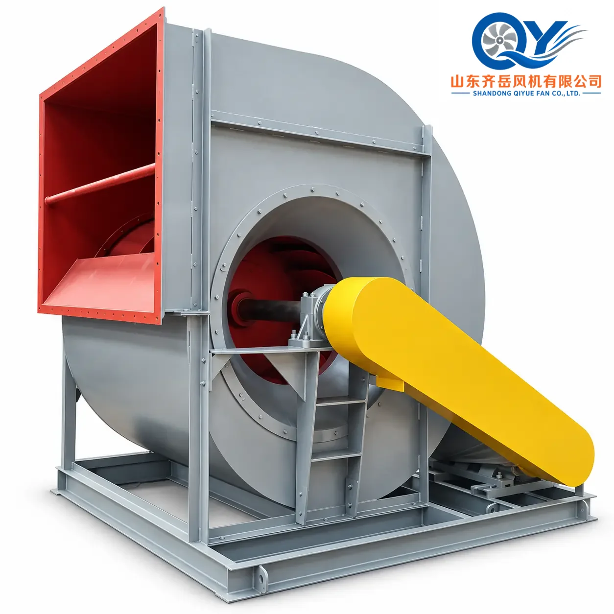
The C6-2×51 dust collection centrifugal fan is a plant-scale fan series developed for large-volume metallurgical dust extraction, particularly smelting dust removal systems in iron and steel plants.
Published No.20F–31.5F configurations cover airflow up to approximately 1.55 million m³/h and total pressure up to 8,619 Pa. Selection should be based on the complete system duty point, gas conditions, collector resistance and installation layout rather than model size alone.

The Fan Must Match the Complete Dust Collection System
A large-flow dust collection fan does not work independently. It provides the draft needed to move process air through capture hoods, branch ducts, the main duct network, dust separation equipment and the final exhaust path.
For an overview of the complete route from dust source to system fan, review the Industrial Dust Collection System guide.
Large-Flow Dust Extraction for Steel & Metallurgical Plants
The original C6-2×51 product documentation identifies iron and steel smelting dust removal equipment as the primary duty. Where operating conditions are comparable, the fan may also be reviewed for other large industrial exhaust or boiler induced-draft duties.
Steel Smelting Dust Extraction
Centralized extraction systems requiring very large airflow from metallurgical production areas.
Large Baghouse Systems
High-volume systems where collector and loaded-filter resistance form a significant part of fan pressure demand.
Metallurgical Process Exhaust
Large process-air duties requiring substantial flow, pressure and engineered foundation support.
Boiler Induced Draft
Possible where the actual boiler and flue-gas duty falls within the published C6-2×51 operating envelope.
Why C6-2×51 Is Different from a General Dust Collection Fan
The series begins at No.20F and extends to No.31.5F. Its airflow, motor-power requirement, foundation load and overall size place it in a plant-scale engineering category rather than general factory ventilation.
Do Not Select a C6-2×51 by Airflow Alone
Fan size and power depend on the operating point created by airflow and total system resistance. Gas temperature, density, altitude, dust condition and duct arrangement can move the real duty point significantly.
If project airflow has not yet been established, start with the Dust Collection System Airflow Calculation .
Define Airflow
Confirm capture demand and simultaneously operating collection points.
Calculate Resistance
Include ducts, fittings, dampers, collectors and final exhaust resistance.
Correct Gas Density
Temperature, altitude and gas composition affect pressure and power.
Check Curve
Match the corrected operating point with fan size and rotational speed.
Engineer Installation
Confirm motor, foundation, bearing support, connections and access.
C6-2×51 No.20F–31.5F Performance Range
Published values are based on inlet pressure of 101325 Pa, inlet temperature of 120°C and medium density of 0.894 kg/m³. Final performance must be corrected to the actual project conditions.
C6-2×51 No.20–31.5F Series Selection Curve
After airflow and corrected total pressure are established, the original series curve can be used to identify the appropriate fan-size and rotational-speed region.

No.20–31.5F Outline & Installation Arrangement
The engineering drawing shows the relationship between the casing, impeller, bearing supports, motor installation area, foundation, inlet flexible connection and outlet flexible connection.
For a fan of this scale, the drawing should be reviewed together with the plant GA drawing, duct interfaces and civil foundation before production.

Connection & Overall Dimensions
Published dimensions support preliminary duct and plant-layout review. Final duct fabrication and civil works should use the approved production drawing for the selected configuration.
Engineering Review Before Production
At this fan scale, performance selection and mechanical installation must be reviewed together. Foundation, motor, duct interfaces and maintenance access can materially affect the final project configuration.
Foundation Loads
Fan mass, dynamic load, anchor bolts and bearing supports should be coordinated with civil design.
Flexible Connections
Duct loads should not be transferred directly to the fan casing. Inlet and outlet connections require independent review.
Motor & Starting
Voltage, frequency, motor power, starting method and site electrical capacity should be confirmed early.
Gas Temperature
Temperature changes gas density and may affect system pressure, material choice and thermal expansion.
Monitoring
Bearing temperature, vibration and operating protection can be reviewed according to project requirements.
Maintenance Access
Reserve sufficient space for bearing service, rotor handling, motor removal and site lifting equipment.
What to Send for C6-2×51 Fan Selection
A reliable quotation requires enough information to verify performance, motor power, connection interfaces and installation conditions.
Airflow, m³/h
Total or static pressure, Pa
Normal / maximum temperature
Gas composition
Dust characteristics
Site altitude
Duct dimensions
Duct layout / GA drawing
Fan position
Foundation restrictions
Available installation space
Required dampers / connections
Voltage / frequency / phase
Starting or VFD requirement
Operating mode
Quantity
Destination country
Required delivery schedule
C6-2×51 Dust Collection Centrifugal Fan FAQ
What is the C6-2×51 centrifugal fan mainly used for?
Its primary published application is smelting dust removal equipment in iron and steel plants, especially very large centralized extraction systems.
What is the maximum airflow of the C6-2×51 series?
The published No.31.5F performance range reaches approximately 1,550,000 m³/h.
Can I select the fan only from airflow?
No. The operating point should combine airflow with complete system resistance and be corrected for gas density, temperature and site conditions.
What is the maximum published gas temperature?
The original product data specify a conveyed-medium temperature not exceeding 250°C.
Is C6-2×51 suitable for a baghouse dust collector?
It may be used where the calculated airflow and total resistance fall within the fan's operating range. Loaded-filter pressure drop must be included in the selection.
Does the listed fan weight include the motor?
No. The published fan-weight data shown on this page exclude the motor.
Can QIYUE FAN match the motor to the project voltage and frequency?
Yes. Final motor configuration can be reviewed according to required power, project voltage, frequency, phase and starting method.
What information is required for a replacement fan project?
Send the existing nameplate, duty point, motor data, inlet and outlet sizes, overall dimensions, foundation information, rotation and site photographs where available.
Send the Duty Point + Duct Layout
QIYUE FAN can review fan size, operating speed, motor power, project voltage, duct interfaces and preliminary installation requirements before quotation.
Tel / WeChat / WhatsApp: +86 15653305981 | Email: sales@qiyuefan.com
Hot Tags: c6-2×51 large-flow dust collection centrifugal fan, China c6-2×51 large-flow dust collection centrifugal fan manufacturers, suppliers, factory


