
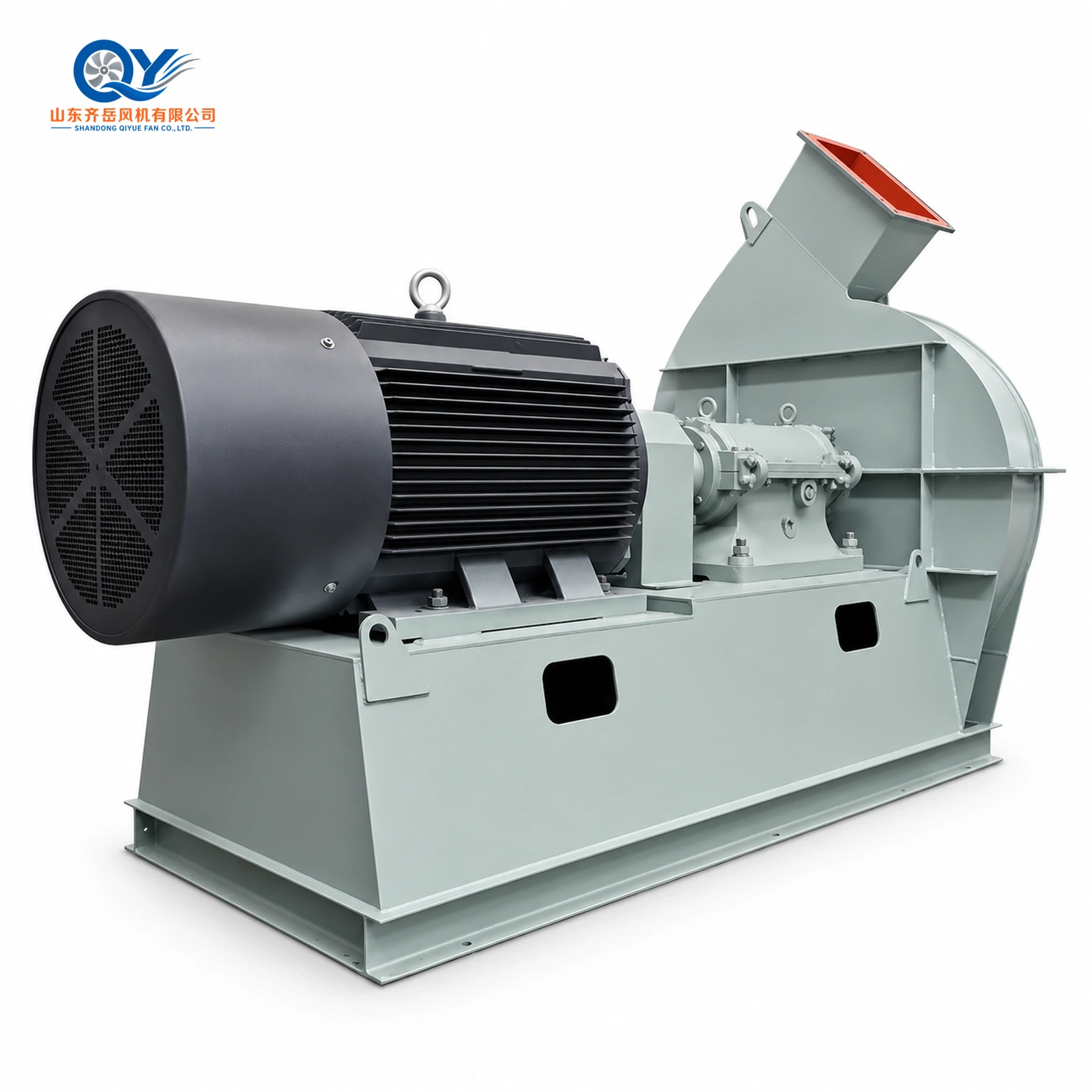
9-18 High-Pressure Centrifugal Fan

9-18 High-Pressure Centrifugal Fan

The 9-18 is a broad-range high-pressure centrifugal fan for industrial forced draft, furnace combustion air, process-air systems and material conveying. The documented No.4A–25F series covers A, D and F arrangements, approximately 797–157,654 m³/h airflow, total pressure up to about 21.1 kPa and motor power up to 1250 kW.
Send Inquiry
Description
Industrial Forced Draft · Furnace Air · Process Air
9-18 High-Pressure Centrifugal Fan
 

The 9-18 is a broad-range high-pressure centrifugal fan series for industrial forced draft, furnace combustion air, process-air systems, material conveying and other applications where substantial airflow must overcome significant system resistance.

The documented range extends from No.4A to No.25F, with A, D and F arrangements, approximately 797–157,654 m³/h airflow and published total pressure up to approximately 21.1 kPa.

Select the fan from the actual airflow, pressure, medium condition and installation requirement rather than from the model number alone.

9-18 high pressure centrifugal fan for furnace forced draft and industrial process air
Representative 9-18 industrial high-pressure centrifugal fan configuration
Airflow
797–157,654
m³/h
Total Pressure
3,168–21,067
Pa
Fan Speed
730–2900
r/min
Efficiency
67.6–76.3%
internal efficiency
Motor Power
3–1250
kW
Configurations
A / D / F
No.4–25
 
Product Position

High-Pressure Fan for Furnace Forced Draft and Industrial Process Air

The 9-18 series covers a much wider capacity range than a single-duty high-pressure blower. Documented sizes extend from No.4A to No.25F and use different fan speeds and mechanical configurations as airflow and power increase.

The original catalogue lists small and medium fertilizer production equipment, cupola furnaces, combustion furnaces, positive-pressure oil-fired furnaces, material conveying, grain conveying and industrial air delivery among its intended duties.

The medium should generally be non-corrosive, non-spontaneously combustible, non-explosive and free from sticky substances. Catalogue guidance states a medium temperature generally not exceeding 80°C and dust concentration not exceeding 150 mg/m³.

 
Technical Specification

9-18 Series Technical Parameters

Fan Sizes
No.4A–25F
Arrangements
A / D / F
Airflow
797–157,654 m³/h
Total Pressure
3,168–21,067 Pa
Efficiency
67.6–76.3%
Fan Speed
730 / 960 / 1450 / 2900 rpm
Medium Temperature
Generally ≤80°C
Dust Concentration
≤150 mg/m³
Reference Temperature
20°C
Reference Density
1.2 kg/m³
Atmospheric Pressure
101325 Pa
Motor Range
3–1250 kW
 
Detailed Performance Table

9-18 Fan Performance by Size and Speed

Each original catalogue block contains eight operating points. To keep the online table usable, the eight points for each fan size and speed are shown below as the exact published minimum-to-maximum envelope.

Across the eight catalogue points, internal efficiency follows the published sequence 69.5%, 73.8%, 75.9%, 76.3%, 75.9%, 74.8%, 72.0% and 67.6%.

Size
Type
Speed
Airflow m³/h
Total Pressure Pa
Efficiency
Required Power kW
Motor kW
4A
A
2900
797–1,951
3,688–4,161
67.6–76.3%
1.6–3.4
3 / 4
4.5A
A
2900
1,134–2,777
4,667–5,267
67.6–76.3%
2.6–5.9
5.5 / 7.5
5A
A
2900
1,556–3,810
5,762–6,702
67.6–76.3%
4.5–10.8
7.5 / 11
5.6A
A
2900
2,186–5,353
7,228–8,156
67.6–76.3%
7.5–17.6
15 / 18.5
6.3A
A
2900
3,113–7,621
9,148–10,323
67.6–76.3%
13.6–31.6
30 / 37
7.1D
D
2900
4,456–10,909
11,618–13,111
67.6–76.3%
24.6–57.5
55 / 75
8D
D
2900
6,374–15,606
14,750–16,645
67.6–76.3%
44.8–104.4
90 / 110
8D
D
1450
3,187–7,803
3,688–4,161
67.6–76.3%
5.8–13.1
11 / 15
9D
D
1450
4,538–11,110
4,667–5,267
67.6–76.3%
10.1–23.5
18.5 / 30
10D
D
1450
6,225–15,240
5,762–6,502
67.6–76.3%
17.1–39.8
30 / 45
11.2D
D
1450
8,745–21,411
7,228–8,156
67.6–76.3%
30.1–70.2
55 / 75
11.2D
D
960
5,790–14,176
3,168–3,575
67.6–76.3%
8.7–20.4
15 / 22
12.5D
D
1450
12,158–29,765
9,003–10,159
67.6–76.3%
52.1–121.6
90 / 132
12.5D
D
960
8,049–19,707
3,946–4,453
67.6–76.3%
15.1–35.3
22 / 37
14D
D
1450
17,081–41,818
11,293–12,744
67.6–76.3%
91.8–214.3
132 / 220
14D
D
960
11,309–27,687
4,950–5,586
67.6–76.3%
26.7–62.2
45 / 75
16D
D
1450
25,497–62,423
14,750–16,615
67.6–76.3%
179.0–417.8
250 / 410
16D
D
960
16,880–41,328
6,466–7,296
67.6–76.3%
52.0–121.2
90 / 132
18F
F
1450
36,303–88,879
18,669–21,067
67.6–76.3%
322.7–752.9
680 / 850
18F
F
960
24,035–58,844
8,183–9,436
67.6–76.3%
93.6–218.5
185 / 220
20F
F
960
32,970–80,719
10,103–11,400
67.6–76.3%
158.6–370.0
280 / 380
20F
F
730
25,071–61,380
5,842–6,592
67.6–76.3%
69.7–162.7
110 / 180
22.4F
F
960
46,320–113,404
12,673–14,301
67.6–76.3%
279.5–652.1
520 / 680
22.4F
F
730
35,223–86,234
7,328–8,269
67.6–76.3%
122.9–286.7
210 / 310
25F
F
960
64,394–157,654
15,785–17,813
67.6–76.3%
483.9–1,129.2
850 / 1250
25F
F
730
48,966–119,882
9,128–10,300
67.6–76.3%
212.8–496.5
370 / 500
Reference condition: inlet air temperature 20°C, density 1.2 kg/m³ and atmospheric pressure 101325 Pa. Final motor selection should be checked at the actual operating point rather than from maximum catalogue values alone.
 
Mechanical Configuration

A, D and F Configurations

A TYPE

No.4A–6.3A

Used for the smaller documented sizes. Separate A-type installation dimensions are provided below.

D TYPE

No.7.1D–16D

Mid-to-large range with separate shaft and bearing support. Detailed installation dimensions are provided below.

F TYPE

No.18F–25F

Large-capacity configurations. Final project dimensions should be confirmed from the selected F-type production drawing.

 
Installation Dimensions · A Type

9-18 No.4A–6.3A Installation Dimensions

The small-size dimensional schedule is shared by the 10-18, 9-18 and corresponding 9-16 family sizes in the original catalogue. Values below are the 9-18 rows. Dimensions are in millimetres unless stated otherwise.

9-18 No.4A to 6.3A centrifugal fan outline and installation dimensions
Inlet and Outlet Interface Dimensions
Size
D1
D2
D3
Inlet Holes
A1
A2
A3
A4
A5
A6
x
y
Outlet Holes
4A
180
205
230
8-Φ7
128
160
182
92
126
148
4
3
14-Φ7
4.5A
200
225
250
8-Φ7
144
176
198
104
135
160
4
3
14-Φ7
5A
224
254
284
8-Φ7
160
192
214
115
150
171
4
3
14-Φ7
5.6A
250
280
310
8-Φ10
179
212
233
129
162
185
4
3
14-Φ7
6.3A
280
320
360
8-Φ10
202
236
258
145
180
204
4
3
14-Φ7
Overall and Foundation Dimensions
Size
E
F
G
K
M
N
a
b
c
d
e
f
Anchor Bolt
Weight kg
4A
100
262
587
286
715
420
200
350
50
300
385
35
M12×300
44
4.5A
110
295
661
322
782
450
200
390
50
300
430
39
M12×300
59
5A
126
328
734
358
868
500
280
450
50
380
495
43
M12×300
72
5.6A
140
367
821
401
962
551
350
485
50
450
534
48
M12×300
104
6.3A
157
413
925
451
1085
620
450
570
60
570
626
55
M16×400
150
Catalogue weights exclude the motor.
 
Installation Dimensions · D Type

9-18 No.7.1D–16D Installation Dimensions

The D-type schedule below uses the 9-18 rows from the shared 10-18 / 9-18 / 9-16 installation table. Dimensions are in millimetres unless stated otherwise.

9-18 No.7.1D to 16D centrifugal fan outline and installation dimensions
Inlet and Outlet Interface Dimensions
Size
D1
D2
D3
Inlet Holes
A1
A2
A3
A4
A5
A6
x
y
Outlet Holes
7.1D
315
355
395
8-Φ10
227
270
293
163
204
232
4
3
14-Φ10
8D
355
395
435
8-Φ10
256
296
322
184
228
253
4
3
14-Φ10
9D
400
450
500
8-Φ12
288
330
354
207
252
276
5
4
18-Φ10
10D
450
500
550
8-Φ12
320
360
386
230
276
299
5
4
18-Φ10
11.2D
500
560
620
12-Φ12
359
415
448
258
316
350
5
4
18-Φ12
12.5D
560
620
680
12-Φ12
400
456
489
288
344
380
6
4
20-Φ12
14D
630
690
750
12-Φ12
448
516
557
332
405
444
6
5
22-Φ12
16D
710
770
830
16-Φ12
512
574
621
368
440
484
7
5
24-Φ12
Overall / Foundation Dimensions
Size
E
F
G
K
L
M
H
a
b
c
d
e
f
g
h
7.1D
177
466
1042
509
1230
1278
280
520
440
300
590
510
193
251
61
8D
200
525
1173
572
1256
1428
280
520
440
303
590
510
207
265
61
9D
226
590
1318
644
1289
1586
280
520
440
310
590
510
223
281
61
10D
250
656
1464
715
1317
1748
280
520
440
314
590
510
239
297
61
11.2D
280
735
1641
801
1565
1947
375
700
620
366
780
700
261
319
61
12.5D
313
820
1830
895
1603
2156
375
700
620
372
780
700
282
340
61
14D
350
920
2050
1001
2031
2400
500
900
900
478
1000
1000
336
436
112
16D
400
1050
2340
1144
2091
2735
500
900
900
488
1000
1000
372
472
112
D-Type Mounting Hardware and Approximate Fan Weight
Size
Bearing-Seat Anchor
Casing Anchor
Rolling Bearing
Weight kg*
7.1D
M24×630
M20×500
1616
453
8D
M24×630
M20×500
1616
490
9D
M24×630
M20×500
1616
583
10D
M24×630
M20×500
1616
639
11.2D
M30×800
M20×500
3620
1053
12.5D
M30×800
M20×500
3620
1162
14D
M36×1000
M30×800
3624
2016
16D
M36×1000
M30×800
3624
2849
*Catalogue weight excludes the motor and foundation bolts.
Discharge orientations
The shared D-type installation schedule provides right-hand outlet references for 0°, 45°, 90°, 135°, 180° and 225°. The N / i / j centre-height dimensions vary with outlet angle, so the final project drawing should be confirmed after the required discharge direction is selected.
 
Typical Applications

Furnace Forced Draft, Process Air and Material Conveying

Furnace Forced Draft

High-pressure combustion and process air for industrial furnaces. For system-level duty and resistance review, see the Industrial Forced Draft Fan System.

Cupola Furnace Air

Pressure-oriented air delivery for cupola-furnace systems.

Process Air

Industrial process-air duties with substantial system resistance.

Material Conveying

Air supply for reviewed material-conveying systems. For clean-air conveying design inputs and system-resistance review, see the Industrial Pneumatic Conveying Air System.

Grain Conveying

Catalogue-listed grain-conveying application subject to system review.

Fertilizer Production

Supporting equipment for small and medium fertilizer-production lines.

 
Selection Logic

How to Select the 9-18 Fan

01

Airflow

Required m³/h or CFM.

02

Pressure

Static or total pressure.

03

Size & Speed

Match the duty point to the performance table.

04

Motor

Check required power and project margin.

05

Installation

Confirm outlet orientation and foundation dimensions.

If the required airflow or system pressure is not yet confirmed, start with the Industrial Fan Selection Guide before comparing individual high-pressure fan series.

 
Related Selection Paths

Related High-Pressure Fan Series

9-16 High-Pressure Centrifugal Fan

View 9-16 →

10-18 High-Pressure Centrifugal Fan

View 10-18 →

10-08-31 High-Pressure Centrifugal Fan

View 10-08-31 →

10-24 High-Pressure Centrifugal Fan

View 10-24 →

6-30 High-Pressure Process Air Centrifugal Fan

View 6-30 Process Air Fan →

High-Pressure Centrifugal Fans

Compare High-Pressure Fans →
 
Buyer FAQ

9-18 High-Pressure Fan FAQ

What airflow range does the 9-18 cover?

Published catalogue data cover approximately 797–157,654 m³/h.

What is the maximum published total pressure?

The highest published value in the supplied 9-18 performance tables is approximately 21,067 Pa.

What sizes are available?

The documented range covers No.4A through No.25F using A, D and F arrangements.

What medium temperature is allowed?

The original catalogue states that medium temperature generally should not exceed 80°C.

Can motors be supplied for overseas voltage and frequency?

Yes. Motor voltage and frequency can be matched to the destination-market requirement after the operating point is confirmed.

Are the 9-18 and 10-18 installation drawings shared?

For the size ranges identified in the original catalogue, yes. The performance tables remain series-specific and should not be interchanged.

Project-Based Fan Selection

Send Airflow + Pressure Before Choosing the Fan Size

Send airflow, pressure, medium temperature, gas or material condition, voltage, frequency, required outlet direction and quantity. QIYUE FAN can review the appropriate fan size, speed, configuration and motor.

QIYUE FAN
 
Industrial High-Pressure Centrifugal Fan Manufacturer
Tel / WeChat / WhatsApp: +86 15653305981   |   Email: sales@qiyuefan.com

Hot Tags: 9-18 high-pressure centrifugal fan, China 9-18 high-pressure centrifugal fan manufacturers, suppliers, factory

Send Inquiry