
MJG Gas Booster Fan For Coal Gas Pressurizing

MJG Gas Booster Fan For Coal Gas Pressurizing

MJG Gas Booster Fan for Coal Gas Pressurizing is a heavy-duty centrifugal blower designed for coal gas, coke oven gas, blast furnace gas, converter gas, biogas, methane and other industrial gas boosting systems. The fan can be configured with D-type coupling drive, enhanced shaft sealing, explosion-proof motor, heavy-duty base and customized inlet/outlet direction according to project requirements. It is suitable for steel plants, coke plants, gas stations, industrial furnaces and combustible gas delivery systems where stable pressure rise and reliable gas leakage control are required.
Send Inquiry
Description
MJG Series / Coal Gas Pressurizing Centrifugal Fan

MJG Gas Booster Centrifugal Fan
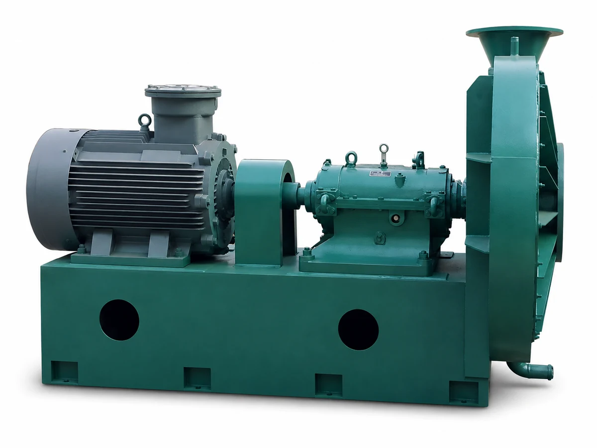
D-type coupling-driven centrifugal gas booster fan for coal gas pressurizing and delivery systems, including blast furnace gas, coke oven gas, converter gas, biogas and related industrial process-gas duties.
MJG gas booster centrifugal fan with motor and coupling drive
Handbook Airflow Range
768–35,200 m³/h
Across listed MJG operating points
Total Pressure Range
4,112–25,820 Pa
Handbook reference data
Motor Power
5.5–250 kW
Model and duty dependent
Drive Arrangement
D-Type Coupling
2900 / 2950 / 2960 r/min
On This Page
Selection Focus
Gas composition
Actual flow
Pressure rise
Gas temperature
Sealing requirement
Hazardous area
01 / Product Overview

Centrifugal Booster Fan for Coal Gas Pressurizing and Delivery

The MJG series is a centrifugal gas booster fan developed for coal-gas pressurizing and conveying systems. The handbook lists applications including coal gas stations, blast furnace gas, coke oven gas, converter gas, biogas and gas transportation in fertilizer-production processes.

The series uses a D-type coupling-drive structure. Compared with ordinary ventilation service, MJG selection requires additional attention to sealing, gas composition, pressure condition and the electrical configuration used around the gas system.

According to the product handbook, the fan is characterized by low noise, relatively low energy consumption, good sealing performance, stable operation, a wide flow-adjustment range and high efficiency.

Important selection boundary: do not select an MJG gas booster fan only from motor power or fan model. Gas composition, actual operating flow, pressure rise, temperature, sealing and hazardous-area requirements should be confirmed first.
02 / Typical Applications

Industrial Gas Pressurizing Duties

01 / COAL GAS
Coal Gas Stations
Gas pressurizing and delivery in industrial coal-gas systems.
02 / BLAST FURNACE
Blast Furnace Gas
Pressurizing and conveying for steel-plant gas systems.
03 / COKE OVEN
Coke Oven Gas
Gas delivery and pressure-boosting applications associated with coke production.
04 / CONVERTER
Converter Gas
Industrial converter-gas conveying and pressurizing after project review.
05 / BIOGAS
Biogas Systems
Biogas conveying where gas properties, moisture and sealing conditions are confirmed.
06 / PROCESS GAS
Process Gas Transport
Selected gas-transport applications in fertilizer and other industrial processes.
03 / Handbook Construction

Impeller, Casing, Sealing and Motor Arrangement

01 / IMPELLER
Optimized Centrifugal Impeller
The handbook describes the impeller as the core of the fan. Material can be selected from stainless steel or alloy steel according to project requirements, with corrosion resistance and mechanical strength considered.
02 / BALANCING
G4 Dynamic Balance
After forming, the handbook specifies impeller dynamic balancing to G4 level, stated as a higher requirement than the referenced G6.3 level.
03 / CASING
Welded Carbon-Steel Casing
The fan casing is formed and welded from quality carbon steel. Internal epoxy-resin coating is specified in the handbook to improve corrosion resistance.
04 / CONNECTIONS
Process Connections
The handbook shows a G3/4" steam-pipe connection on the upper casing and a G1.5" drain valve at the lower section. Inlet and outlet use standard flange connections.
05 / SEALING
Packing + Centrifugal Seal
The sealing group combines soft packing sealing and centrifugal sealing. The handbook describes the arrangement as simple, reliable and convenient to replace.
06 / MOTOR
Y / YB Series Motor
The original handbook specifies Y-series or YB-series motors. For YB-series explosion-proof motors it lists dⅡBT4 and IP44.
Outlet arrangement: the handbook provides three discharge directions - 0°, 90° and 180° - for matching the actual piping layout.
04 / Handbook Performance Range

MJG Model Range for Preliminary Selection

The original handbook provides multiple operating points for each model. To keep the product page readable, the table below summarizes the minimum and maximum airflow and total-pressure values shown for each model.

Final selection should use the actual operating point rather than selecting only from the range endpoints.

MODEL
RPM
AIRFLOW / PRESSURE
MOTOR / FOUNDATION BOLT
MJG11-500
2900
1,174–2,504 m³/h
4,112–4,684 Pa
5.5 kW
6-M16×400
MJG11-560
2900
1,610–3,488 m³/h
5,080–5,768 Pa
5.5 / 7.5 kW
6-M20×500
MJG12-560
2900
4,293–6,762 m³/h
5,180–6,035 Pa
15 kW
6-M20×500
MJG11-630
2900
2,202–4,901 m³/h
6,400–7,273 Pa
11 / 15 kW
6-M20×500
MJG12-630
2900
6,032–9,500 m³/h
6,521–7,546 Pa
30 kW
8-M20×500
MJG13-630
2950
8,588–13,552 m³/h
8,310–9,698 Pa
45 / 55 kW
8-M20×500
MJG11-710
2900
3,220–6,978 m³/h
8,148–9,265 Pa
18.5 / 30 kW
8-M20×500
MJG12-710
2950
12,292–19,360 m³/h
10,635–12,427 Pa
75 / 90 kW
8-M20×500
MJG11-800
2900
768–2,612 m³/h
11,472–12,471 Pa
11 / 15 kW
8-M20×500
MJG12-800
2900
4,610–9,988 m³/h
10,426–11,868 Pa
37 / 45 kW
8-M20×500
MJG11-860
2960
2,580–6,243 m³/h
12,327–14,802 Pa
37 kW
8-M20×500
MJG12-860
2950
6,538–10,140 m³/h
11,752–14,993 Pa
55 kW
8-M20×500
MJG13-860
2950
9,495–16,318 m³/h
10,879–14,679 Pa
75 kW
8-M20×500
MJG11-900
2950
1,110–3,775 m³/h
14,867–16,163 Pa
22 / 30 kW
6-M16×400
MJG12-900
2950
1,341–4,560 m³/h
17,013–18,496 Pa
30 / 37 kW
8-M20×500
MJG11-950
2950
2,996–7,960 m³/h
16,216–17,096 Pa
45 / 55 kW
8-M22×500
MJG11-1000
2950
1,591–5,412 m³/h
19,073–20,736 Pa
37 / 45 kW
8-M22×500
MJG12-1000
2950
3,832–9,159 m³/h
19,673–20,589 Pa
55 / 75 kW
8-M22×500
MJG11-1100
2950
2,675–9,202 m³/h
19,652–22,748 Pa
75 / 90 kW
8-M22×500
MJG12-1100
2950
4,295–10,225 m³/h
20,803–21,931 Pa
75 / 90 kW
8-M22×500
MJG11-1120
2950
6,592–14,304 m³/h
13,359–15,225 Pa
75 / 90 kW
8-M22×500
MJG12-1120
2950
12,200–19,360 m³/h
10,635–12,420 Pa
75 / 90 kW
8-M22×500
MJG13-1120
2950
17,580–27,700 m³/h
13,630–15,950 Pa
132 / 160 kW
8-M22×500
MJG11-1150
2950
9,210–20,350 m³/h
15,510–16,760 Pa
90 / 110 kW
10-M20×500
MJG12-1150
2950
18,600–29,800 m³/h
16,720–19,480 Pa
160 / 200 kW
8-M22×500
MJG13-1150
2950
23,400–35,200 m³/h
16,800–19,350 Pa
200 / 250 kW
8-M22×500
MJG11-1200
2950
4,813–15,664 m³/h
20,081–23,693 Pa
90 / 110 / 132 kW
8-M22×500
MJG11-1260
2950
6,850–17,380 m³/h
24,200–25,220 Pa
132 / 160 kW
8-M22×500
MJG12-1260
2950
10,950–22,200 m³/h
24,850–25,820 Pa
160 / 200 kW
8-M22×500
Data note: each handbook model contains multiple individual operating points. The values above are the min–max envelope of those listed points and are intended for preliminary screening, not for replacing final fan selection.
05 / Gas-Service Configuration

Gas Tightness and Electrical Configuration Require Project Review

01 / SEAL
Packing Seal
Part of the handbook sealing arrangement used around the shaft region.
02 / SEAL
Centrifugal Seal
Used together with packing sealing in the standard handbook structure.
03 / MOTOR
Y / YB Motor
Motor series is selected according to the project and required electrical configuration.
04 / HANDBOOK
dⅡBT4 / IP44
These are the YB-series explosion-proof grade and protection level stated in the original handbook.
For a current project, provide the required hazardous-area classification, local electrical standard, voltage, frequency and motor requirements. Do not assume that a historical handbook motor designation automatically satisfies a current project specification.
06 / Outline & Installation Dimensions

0°, 90° and 180° Discharge Arrangements

The handbook provides three outlet directions. The drawing below retains the original MJG structure and dimension-symbol system for the inlet flange, outlet flange, bearing section, base and motor arrangement.
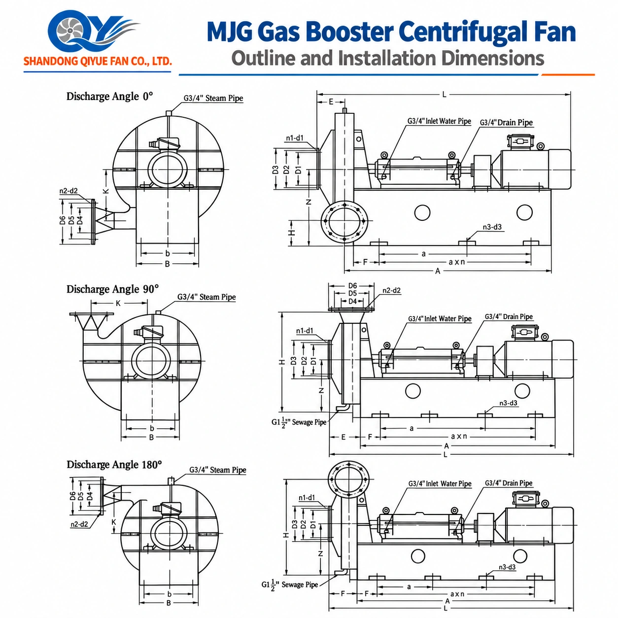
MJG gas booster centrifugal fan outline and installation dimensions
Inlet Flange
D1 / D2 / D3 and n1-d1 define the inlet connection dimensions and bolt pattern.
Outlet Flange
D4 / D5 / D6 and n2-d2 define the discharge flange connection.
Base Dimensions
A, a×n and n3-d3 define major foundation and fixing dimensions.
Overall Envelope
B, b, K and L are model- and motor-dependent outline dimensions.

Discharge Angle Reference Dimensions N / H

MODEL
0° N / H
90° N / H
180° N / H
MJG11-500
540 / 224.5
500 / 860
470 / 785.5
MJG11-560
510 / 200.5
480 / 880
460 / 769.5
MJG12-560
510 / 200.5
480 / 880
460 / 769.5
MJG11-630
550 / 201
530 / 950
500 / 849
MJG12-630
550 / 201
530 / 950
500 / 849
MJG13-630
730 / 279
665 / 1230
600 / 1051
MJG11-710
670 / 223.5
600 / 1050
580 / 1026.5
MJG12-710
810 / 301.5
735 / 1375
670 / 1178.5
MJG11-800
620 / 184
600 / 1120
580 / 1016
MJG12-800
630 / 194
600 / 1120
580 / 1016
MJG11-860
660 / 197.5
620 / 1140
610 / 1072.5
MJG12-860
690 / 230
620 / 1140
610 / 1070
MJG13-860
740 / 285
620 / 1140
610 / 1065
MJG11-900
680 / 190
660 / 1260
650 / 1140
MJG12-900
700 / 190
680 / 1280
660 / 1170
MJG11-950
720 / 200
680 / 1280
670 / 1190
MJG11-1000
730 / 205
700 / 1300
680 / 1205
MJG12-1000
730 / 205
700 / 1300
680 / 1205
MJG11-1100
840 / 224.5
800 / 1550
770 / 1385.5
MJG12-1100
910 / 294.5
800 / 1550
770 / 1385.5
MJG11-1120
870 / 231
840 / 1600
790 / 1429
MJG12-1120
935 / 296
840 / 1600
790 / 1429
MJG13-1120
955 / 316
840 / 1600
790 / 1429
MJG11-1150
945 / 289.5
840 / 1610
810 / 1465.5
MJG12-1150
975 / 319.5
860 / 1630
810 / 1465.5
MJG13-1150
975 / 319.5
860 / 1630
810 / 1465.5
MJG11-1200
860 / 231.5
850 / 1610
780 / 1408.5
MJG11-1260
895 / 234.5
870 / 1650
820 / 1480.5
MJG12-1260
895 / 234.5
870 / 1650
820 / 1480.5
N and H are handbook installation dimensions in millimetres. Other dimensions including D1–D6, E, F, A, B, b, K, L and foundation-hole patterns vary with the selected model and motor configuration.
07 / Selection & RFQ Data

What to Send for MJG Gas Booster Fan Selection

The handbook performance table provides the fan series, but a quotation should be based on the actual process-gas condition and required operating point.

01
Gas Composition
Gas type, major components, moisture, corrosive constituents and any particles.
02
Required Flow
Normal, minimum and maximum operating flow. Clarify whether the value is actual m³/h or another stated reference condition.
03
Pressure Requirement
Inlet pressure, outlet pressure or required fan pressure rise.
04
Temperature
Normal operating temperature together with maximum or abnormal conditions.
05
Sealing Requirement
State the process requirement for gas leakage control and shaft sealing.
06
Motor & Electrical
Voltage, frequency, hazardous-area classification and required motor standard.
07
Outlet Direction
Confirm 0°, 90° or 180° according to the piping arrangement.
08
Installation Data
Pipeline layout, flange requirement, foundation space, altitude, quantity and available maintenance access.
09 / Buyer FAQ

MJG Gas Booster Fan Questions

What is the MJG gas booster fan used for?
The handbook lists coal-gas pressurizing, blast furnace gas, coke oven gas, converter gas, biogas and industrial process-gas conveying applications.
What is the MJG airflow and pressure range?
Across the operating points shown in the supplied handbook, the series covers approximately 768 to 35,200 m³/h and 4,112 to 25,820 Pa. These values are the overall handbook envelope, not one continuous performance curve.
What drive arrangement does MJG use?
The handbook lists D-type coupling drive throughout the supplied MJG performance tables.
What sealing arrangement is used?
The original product description specifies a sealing group using soft packing sealing together with centrifugal sealing.
What outlet directions are available?
The supplied engineering drawing and dimension table provide 0°, 90° and 180° discharge arrangements.
Does the handbook specify an explosion-proof motor?
The handbook states that Y-series or YB-series motors are used and lists dⅡBT4 and IP44 for the YB-series explosion-proof motor configuration. Current project requirements should still be confirmed separately.
Can you provide the final outline drawing for a selected model?
Yes. The handbook dimensions depend on the fan model, motor size and discharge direction. Confirm the selected duty point and motor configuration before using dimensions for foundation or duct fabrication.
What information is required for quotation?
Send gas composition, operating flow, inlet and outlet pressure or required pressure rise, temperature, sealing requirement, motor voltage and frequency, hazardous-area requirement, discharge direction and installation layout.
MJG Gas Booster Fan Selection

Send the Gas Conditions and Required Operating Point.

Gas Composition · Airflow · Inlet Pressure · Outlet Pressure · Temperature · Sealing Requirement · Hazardous Area · Voltage / Frequency · Outlet Direction · Installation Layout
Manager Zhao
SHANDONG QIYUE FAN CO., LTD.
Industrial fan selection and export project support

Hot Tags: mjg gas booster fan for coal gas pressurizing, China mjg gas booster fan for coal gas pressurizing manufacturers, suppliers, factory

Send Inquiry